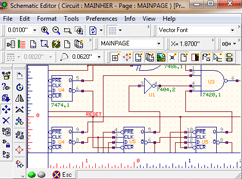
Schematic Editor
Schematic Editor is the front end for any PCB design application.
Schematic Editor of EDWinXP allows to capture the circuit in the form of a
schematic diagram. The created circuit is in the form of a logical diagram where
components are placed using the
Library Browser and Library Explorer. Each of the components
placed is labeled which displays information about the symbol. These components
are then packed to extract the package assigned at the time of part creation. It
provides the facility to perform both Manual and Automatic operations. It also
provides tools to add text information to the circuit, thereby increasing its
readability.

 Creating Schematic Diagram
 Page Configuration
 Loading Components
 Autoplacing and Packing Components
 Establishing Connections
The electrical connections between component entries are established using
Wires/ Buses or Nets. Automatic operation like
Packing, Placing components
and Routing is also possible from within this editor. The properties of the
objects placed may be accessed after selecting the objects using Ctrl key and a
click. Once when a schematic diagram is complete, necessary notes may be added
by selecting appropriate tools. This Editor also allows editing already existing
databases. The circuit thus captured is automatically front annotated to the
Layout mode.
Schematic DXF Export
allows to export the EDWin XP/2000 Schematic graphics to Autocad DXF format.
Analysis is an important part of any design process. Circuit Analysis involves
testing the performance of the circuit for different DC operating points and
with signal applied, over a range of output levels, supply voltages and
temperatures. EDWin XP/2000 provides two types of Mixed mode simulators one is
EDWin XP/2000 Mixed Mode Simulator and other is EDSpice Simulator which adheres
to the SPICE Standards.
