Establishing Connections for the Circuit

Connections between components are established using WIRES and BUSES.
Select ![]() Connections from Tools toolbar to enable a set of tools required for
routing.
Connections from Tools toolbar to enable a set of tools required for
routing.
![]() Tip:
Adjust zoom precision to view the terminals being wired. Turn ON
grid and snap to help in positioning the wires.
Tip:
Adjust zoom precision to view the terminals being wired. Turn ON
grid and snap to help in positioning the wires.
1. Creating the data bus
Select the second Function tool ![]() Create Bus, click on the workspace and drag the cursor and left click
when the bus has the required length, right click and press
Create Bus, click on the workspace and drag the cursor and left click
when the bus has the required length, right click and press ![]() End Bus. An input box appears, enter a name for the bus, say Data bus.
End Bus. An input box appears, enter a name for the bus, say Data bus.
The wire connections may now be created in the following way. Before creating
the connections, enable the two menus Preferences / Instant net name and
Preferences /Instant wire label. Right click and select tool ![]() Connect component.
Connect component.
2. Routing the wire connections
a. Enable
Pin to Pin whenever an entry or pin is clicked for making a connection. This ensures that the connection is made to the pin.
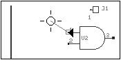
Fig. 4.11
An input box appears prompting the user to enter the name of
the net, enter A,n (simply entering A will also suffice). Now select Option
tool ![]() Snap Wire by 90 degree and click on the workspace where the wire
segment has to be bent, now unselect this tool, enable the option tool
Snap Wire by 90 degree and click on the workspace where the wire
segment has to be bent, now unselect this tool, enable the option tool ![]() Allow T-connections and click on the Bus. An input box will ask which
member of the bus the wire has to be connected to, enter ‘0’. A
text ‘0’ is tagged to the cursor, place it near the wire.
Allow T-connections and click on the Bus. An input box will ask which
member of the bus the wire has to be connected to, enter ‘0’. A
text ‘0’ is tagged to the cursor, place it near the wire.
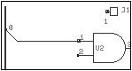
Fig. 4.12
b. Repeat the same process for the second input pin of the AND Gate, in this case give the net name B.
c. Repeat the same process for the first input pin of the XOR Gate. Give the net name A,
d. EDWin gives a message “Connect to existing Net : A”. Press “Yes”.
e. Repeat the same process for the second input pin of the XOR Gate and give the net name B.
f. Enable ![]() Pin to Pin (or press F3) and click on the output pin of the AND
Gate, enter net name CARRY, now enable F2, stretch the wire to a suitable
length and left click. Now terminate the connection by pressing END or F4 key
on the keyboard or click on the tool
Pin to Pin (or press F3) and click on the output pin of the AND
Gate, enter net name CARRY, now enable F2, stretch the wire to a suitable
length and left click. Now terminate the connection by pressing END or F4 key
on the keyboard or click on the tool ![]() End Connection.
End Connection.
3. Routing the wire connection without any visible traces
a. Enable the option tool ![]() Connect without wire from
Connect without wire from ![]() Connect component function tool.
Connect component function tool.
b. Click on the pin to start connection. The pin is highlighted and the wire extends with the mouse.
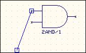
Fig. 4.13
c. Bring the wire end to the required pin and click and then click on ![]() End Connection. The pins as well as the node get highlighted
(Refer Fig. 4.14 & 4.15).
End Connection. The pins as well as the node get highlighted
(Refer Fig. 4.14 & 4.15).
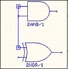
Fig. 4.14
Fig. 4.15
4. Automatic Connection Establishment
Auto routing can take place only if nets exist.
1. Select the option tool ![]() Autoconnect wire to connect a single net or
Autoconnect wire to connect a single net or ![]() Autoconnect all wires to connect selected nets.\
Autoconnect all wires to connect selected nets.\
2. The Autoconnect dialog box pop up and select the required scheme and click apply.
![]() Tips:
To perform any editing operation on the wire drawn, select the wire
by using Ctrl key. Bullets get placed on the wire. Bullets have function such
as Disconnect wire, Insert Bend point, relocation, etc.
Tips:
To perform any editing operation on the wire drawn, select the wire
by using Ctrl key. Bullets get placed on the wire. Bullets have function such
as Disconnect wire, Insert Bend point, relocation, etc.
Entering Net labels
To improve the readability of the circuit, use the option tool
![]() Add
/Edit net / Bus member label from the function tool
Add
/Edit net / Bus member label from the function tool ![]() Edit Connection and click on the wire to be labeled. The net name is tagged
to the cursor. Place the net name at the desired location. Enabling Preferences
/ Instant wire label achieves this but when it comes to bus connections, it
keeps the bus member label instead of the net label. To put the net names in
such cases, use this function tool.
Edit Connection and click on the wire to be labeled. The net name is tagged
to the cursor. Place the net name at the desired location. Enabling Preferences
/ Instant wire label achieves this but when it comes to bus connections, it
keeps the bus member label instead of the net label. To put the net names in
such cases, use this function tool.
Operations that may be performed on a Net
- Splitting Nets
This function tool may be used to split a net into two parts.
When a net is split then the portion of the net from its starting point to the point of split will retain the same net name whereas the remaining nodes will be assigned to a new net. The new net is automatically assigned a name, which may be changed
- Merging Nets
Existing nets may be merged using this facility. While merging, priority is given to PWR/GND, named and then to unnamed net.
- Merging Nets
Allows deleting a node or a whole Net.
- Net Properties
Displays the properties of a selected Net, like Net name, status, bus member etc.