Adder Subtractor
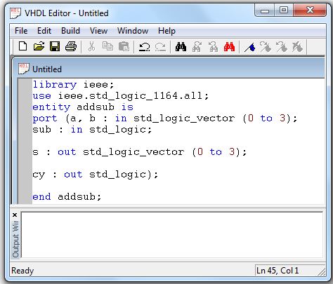
- Right Click on System from Project Explorer and select VHDL Editor from the List
- Enter the following code in the workspace provided in the VHDL Editor window
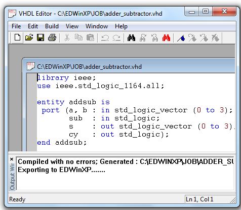
- Save the file (.vhd) and compile the code using Compile & Import option from Build menu.It compiles the source file and generates wirelist (*.wrs) output file
- Output window shows the status of errors
- Click on Import button in Netlist/Wirelist Export&Import window.
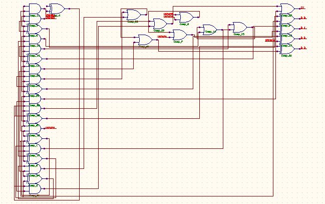
- Open Schematic Editor,Autoplace the components by selecting Tools|Autoplace.
- Autoconnect the components by selecting menu Tools|Connections.Select option tool Autconnect all wires from Connect components
- Pcb layout creation is not possible for a schematic using vhdl as its component part includes only symbol hence couldn't pack components.
library ieee;
use ieee.std_logic_1164.all;
entity addsub is
port (a, b : in std_logic_vector (0 to 3);
sub : in std_logic;
s : out std_logic_vector (0 to 3);
cy : out std_logic);
end addsub;
architecture addsub_a of addsub is
signal cry : std_logic_vector (0 to 2);
signal c : std_logic_vector (0 to 3);
begin
process (sub, a, b)
begin
c(0) <= b(0) xor sub;
c(1) <= b(1) xor sub;/p>
c(2) <= b(2) xor sub;
c(3) <= b(3) xor sub;
s(0) <= (c(0) xor a(0)) xor sub;
cry(0) <= (c(0) and a(0)) or (c(0) and b(0)) or (a(0) and b(0));
s(1) <= (c(1) xor a(1)) xor cry(0);
cry(1) <= (c(1) and a(1)) or (c(1) and b(1)) or (a(1) and b(1));
s(2) <= (c(2) xor a(2)) xor cry(1);
cry(2) <= (c(2) and a(2)) or (c(2) and b(2)) or (a(2) and b(2));
s(3) <= (c(3) xor a(3)) xor cry(2);
cy <= (c(3) and a(3)) or (c(3) and b(3)) or (a(3) and b(3));
end process;
end addsub_a;