New features from EDWinXP ver 1.40 to EDWinXP 1.50
New Features of EDWinXP 1.40 – What’s New
Schematic Editor
1. Block Diagram Elements
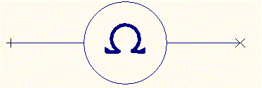
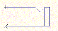
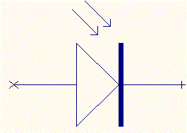
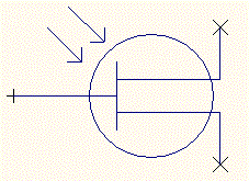
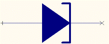
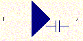
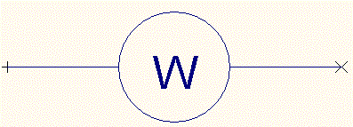
This feature allows for simplified creation of block diagrams of hierarchical circuits. There is no longer need to create block diagram elements using Library Editor since part descriptions and symbols are automatically created according to user’s specification. Nevertheless, parts and symbols created for block diagram elements may be edited like any other library element and stored in the disk libraries for farther use.
2. Component Specific MM Simulator Models
Mixed Mode simulation models may be assigned individually to components, hence overriding current model assignment to symbols. Component specific simulation models may be assigned to block diagram elements.
3. Truth Table to diagram converter
Logic function defined in form of truth tables may be converted to equivalent schematic diagram that may be later attached to currently edited page, form a new page in edited circuit or be attached as new circuit in the project.
4. Direct assignment of logic function to schematic components
Logic function of selected schematic component may be specified either through truth table or VHDL code and attached in form of hierarchical sub-circuit or automatically generated simulation model. Generation of both MM Simulator and EDSpice code models is supported.
5. VHDL Code Converter
This function enables conversion of VHDL code into schematic diagram.
6. Vertically or horizontally oriented net/bus page link notes
Depending on user’s preference, net/bus page link notes may be generated either as vertical or horizontal bar. Vertical bar was the only option in previous versions.
Mixed Mode Simulator & EDSpice Simulator
1. Instant Probes
These probes are used for instant display of transient analysis result of desired nets/nodes in an analog/digital circuit.
2. 8051 Microcontroller Kit
The kit contains new simulation model of microcontrollers of 8051 family and application examples. The 8051 model uses MMI technology that enables edition and compilation of programs in C-language and assembler, debugging the code and simulation together with whole circuit. Attached simulation examples help in evaluating the kit and learning how to use the model for the development of microcontroller programs. The kit contains also series of so called instrumental model for generating parallel and serial binary data patterns and asynchronous hardware interrupts. Usage of 8051 model in user’s designs requires separate license.
This kit includes example project databases designed to illustrate functionality of the new simulation model for 8051 microcontrollers. Each project comes with associated help file that explains the example in details.
The latest software version of the model is included as well as 8051 code C compiler and function libraries. The new MMI model for 8051 allows coding programs in C or Assembler and debugging them in real time while functioning of the rest of circuitry is simulated.
To facilitate analysis of more complex microcontroller based circuits, the kit includes also several instrumental MMI models such as memories, interrupt generators, serial/parallel pattern generators, 7-segment displays etc. The Multifunction Model Interface (MMI) dialog for 8051 model supports following features: • C Editor
• Assembly Editor
• Listing View
• Hex Editor
• Disassembler
• Output File
• Errors and Warnings
3. AVR Microcontroller Kit
This kit includes example project databases designed to illustrate functionality of the simulation model for AVR AT90S2313 Microcontroller. Each project comes with associated help file that explains the example in details.
The new MMI model for AVR AT90S2313 allows coding programs in C or Assembler and debugging them in real time while functioning of the rest of circuitry is simulated.
Users can design complex microcontroller based circuits with the use of instrumental MMI models such as memories, interrupt generators, serial/parallel pattern generators, 7-segment displays etc.
The Multifunction Model Interface (MMI) dialog for AVR AT90S2313 Model includes the following modules: • C Editor
• Assembly Editor
• Listing View
• Hex Editor (ROM)
• Hex Editor (EEPROM)
• Disassembler
• Output File
• Errors and Warnings
MM Simulation Model Generator
1. Analog Model Type
MM Simulation Model Generator enables to generate models of analog circuit elements. The logic function of analog elements may be very precisely described in so-called SPICE netlist format. Therefore the source for analog model generation is ASCII file containing SPICE sub-circuit.
PCB Layout Editor
1. Multilayer copper pour connectivity check with 3D presentation included
Copper pour connectivity check, working in similar way as in Fabrication Manager, has been added to PCB Layout Editor. 3D presentation may be used to visualize detected errors on all layers where tested net connections are located. 2. Improved presentation of copper pours
On request, coppers pour areas may be presented filled by meshed pattern for better visualization of boundaries on densely packed PCB layouts. 3. Auto Connect Functions
Auto-connect tools in Layout Editor are complement to manual trace routing tools. These auto-connect functions work directly on items in the project database. Execution time depends very much on the complexity of the board. Whether routing task is completed successfully depends on topology of currently existing connections.
The new Auto connect tools come under Tools | Connections | Auto Connect Traces are:
Auto Connect Node Pair : Routing connection from node to node.
Auto Connect Net: Routing connections for all nodes in selected net with the option to keep pre-routed traces unaltered.
Auto Connect Net Element: Routing connection from selected net element (existing trace or node) to closest located element in the same net.
Auto Lead-Out from Net Element: Routing lead-out traces from component nodes.
Auto Clear Component Zone: Clearing a zone around a component(s) and re-routing all traces not connected to this component outside of the zone boundaries
Auto Remove Vias: Removing redundant via holes on the whole board
Auto Miter: Mitering all traces on the board in 45 degrees
Fabrication Manager
1. Improved multilayer copper pour connectivity check with 3D presentation
Previously implemented copper pour connectivity check has been enhanced for simultaneous testing of all artwork layers where connections for selected net are present. User may examine location of detected unconnected or isolated pads and isolated via holes with help of two or three dimensional presentation.
2. Polygonal copper relieve
Definition of areas on the artwork where copper should be removed from copper poured Gnd/Power planes was previously done through placing items like rectangles and circles. In present version relieve areas may be defined by polygons. A feature useful for removing of isolated islands of copper that usually have irregular shapes.
3. 3D export in IDF format
Feature allowing for exporting 3D view of the PCB in IDF Ver. 3 format
4. 3D IDF file viewer
Three-dimensional presentations of IDF Ver 3 format files.
5. Automatic Copper Cleanup
Enables removal of all "black" copper areas (isolated areas) from the artwork. The program analyses display of the artwork after test and generates copper relieve items in number and sizes necessary to cover all detected black spots.
6. Semi - automatic copper trimming
Enables to trim isolated "black" copper or connected "red" copper on the board. Trimming is necessary, especially when there are areas of connected (red) copper that are superfluous.
7. Polygonal Copper Relieve
Enables removal of isolated islands of copper that usually have irregular shapes (polygonal shape).
Library Editor
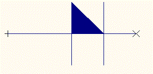
1. Triangular Package and Padstack
Allows to create triangular package and padstack.
3D Graphics
1. User definable true colors
Apart from 32 standard colors, the user may define custom palette of 224 colors and assign them to objects in three-dimensional visualization.
2. Improved scrolling and navigating
Current scroll position is retained when switching between 2D and 3D presentation. This is useful for examining results of connectivity check where alternating views without losing focus on the object is often required. Rotation of 3D view is executed around currently focused location rather then around coordinate system origin.
3. Semi-transparent view of copper pour areas and layout components
An extremely useful feature for 3D visualization of multi layered PCB designs.
What’s new in EDWinXP 1.50
Following release of previous version, several new features and improvement to existing features have been implemented in EDWinXP 1.50
PCB Layout Design and Fabrication
1. Copper pour connectivity test have been added PCB Layout Editor. Similar test was already included in Fabrication Manager. The advantage of this test in Layout Editor is that the connectivity may be checked while the board layout is designed. In both modules, the test may be now performed in selectable accuracy of 0.100, 0.050 and 0.025 mm. The time needed to execute the connectivity test has very significantly reduced.
2. Polygon shapes for copper removal introduced in 1.40, allowed to add feature that automatically removes unnecessary copper in isolated places within copper pour areas. This function was available for 1.40 users through live update. In 1.50, it has been improved in both speed (about 50% reduction of execution time) and accuracy.
3. Gerber View feature has been improved in order to reduce number of selections necessary to pre-process and display artworks in Gerber formats.
4. The option to plot inverted polarity circles and squares in size of pinholes for PMD component and vias has been added for Gerber format output. This option is available for in RS-274-X format only.
5. Settings for all fabrication exports (GenCAM, IDF and newly added Valor’s ODB++ format) have been grouped in common dialog within Fabrication Manager.
6. It is now possible to import projects from other EDA packages in ODB++ format
7. Reconstruction of projects from Gerber format artworks been have significantly improved by adding feature for rebuilding component parts and packages from imported graphics. Projects can be now completely reconstructed even if necessary library elements are not available.
8. Number of tools for automatic routing of connection in PCB Layout Editor has been increased. It is now possible to automatically connect two separate trace branches of a net, re-route connections for a group of relocated components, route lead-out traces from pins of component with complicated pad patterns, automatically miter traces and remove redundant via holes.
9. Online clearance check has been introduced with improved visibility for detected clearance violations.
10. It is now possible to display ratsnest in two modes: will all nodes or with unconnected nodes only.
11. Important function “re-route” trace may be now performed in two modes: “re-route trace segment” and “re-route pin to pin connection. This latter is particularly useful when cleaning up design after auto-routing.
12. Node marker size (squares) and pin entry marker size (crosses) are automatically adjusted to the pitch of component pads in order to ensure best visibility. Similarly, via hole marker size is automatically adjusted to smallest hole diameter in via pad stacks
Schematic Capture and Simulation
1. New feature called Filter Designer has been added. The system library includes prototype circuits for active low-pass, high-pass, band-pass and band-stop filters. Filter Designer allows to select one of the variants of those filters (Chebyshev, Butterworth, Bessel, Elliptic (Cauer) or Universal) and specify required filter output parameters – frequency and quality range. The parameters (capacitance and resistance) for filter circuit components are calculated and updated in the circuit, which subsequently may be appended to the project.
2. It is now possible to convert functional descriptions of discrete parts, expressed in form of SPICE format sub-circuit into analogue model for Mixed Mode Simulator.
3. Following code models have been added to MM Simulator and EDSPice model libraries:
4. New feature called Filter Designer has been added. The system library includes prototype circuits for active low-pass, high-pass, band-pass and band-stop filters. Filter Designer allows to select one of the variants of those filters (Chebyshev, Butterworth, Bessel, Elliptic (Cauer) or Universal) and specify required filter output parameters – frequency and quality range. The parameters (capacitance and resistance) for filter circuit components are calculated and updated in the circuit, which subsequently may be appended to the project.
5. It is now possible to convert functional descriptions of discrete parts, expressed in form of SPICE format sub-circuit into analogue model for Mixed Mode Simulator.
6. PIC Microcontroller Kit
The PIC kit includes main projects with assembler source code, which illustrates the functionality of PIC microcontrollers, with associated help files
The latest software version includes the PIC model and it's function libraries. The new MMI model for PIC allows coding in Assembler Editor and debugging them in real time while simulating with the rest of circuitry.
To facilitate analysis of more complex microcontroller based circuits, the kit also includes, several instrumental MMI models such as serial/parallel pattern generators, interrupt generators, 7-segment displays etc.
The PIC16C5x is the current version included in EDWinXP.
The Multifunction Model Interface (MMI) dialog for PIC model supports following features:
• Assembly Editor
• Listing View
• Hex Editor
• Disassembler
• Output File
• Errors and Warnings
7. Following code models have been added to MM Simulator and EDSPice model libraries:
| EDSPICE code models | MM Simulator models |
| M7218CD | DAC0800 |
| Max456 | ADC0800 |
| Max4587 | MAX232 |
| Max522 | DAC AD 569 |
| max5341 | HPDL1414 |
| max5352 | ULN2003A |
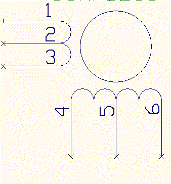
| max625 | Stepper Motor |
| max690 | Potentiometer |
| max691 | LCD Display |
| max696 | LCD Display Driver-HD44780U |
| max697 | SweepGenerator.dll |
| max701 | |
| max702 | |
| max708 | |
| max7225 | |
| MAX7240 |
8. EDSPICE updates for EDWinXP 1.50
Sub-circuit files
• Diac
• CCCS
• CCVS
Circuit files (SPICE netlist format)
• BUCK CONVERTER AC MODEL.CIR
• DC_MOTOR_MODEL.CIR
• TREBLE AND BASS TONE CONTROLS.CIR
• I-TO-V CONVERTER (TRANSIMPEDANCE AMP).CIR
• CCCS.CIR
Sample projects with new EDSPICE sub-circuits
• 7805 Regulator - voltage regulator 7805
• CENTRE TAPPED TRANSFORMER - transformer
• Controlled Full Wave Rectifier - SCR
• OPTOCOUPLER- OPTOCOUPLER
• IGBT - IGBT
• Sidac characteristics - sidac
• UJT Relaxation Oscillator – UJT
• Current Controlled Current Source - CCCS
• Current Controlled Voltage Source – CCVS
Updates in Part Libraries
| PART | MANUFACTURER | SYMBOL | PACKAGE |
| 0805AS-2N7M-01 | Fastron | INDUCTOR | L/L70/SM |
| 59S101-400E3 | Rosenberger | CONN | CON/F5/A |
| 74HC4052D | Philips | MUX4052 | SOIC16/150 |
| 8516-4500 | 3M Interconnect Solutions | CONN | CON/HEADER16/A |
| 8520-4500 | 3M Interconnect Solutions Division | CONN | CON/HEADER16/A |
| 8526-4500 | 3M Interconnect Solutions Division | CONN | CON/HEADER16/A |
| 8540-4500 | 3M Interconnect Solutions Division | CONN | CON/HEADER16/A |
| 8560-4500 | 3M Interconnect Solutions Division | CONN | CON/HEADER16/A |
| A3953SB | Allegro | DRV3953 | DIP16/300 |
| ACSL-6400-T | Agilent Technologies | OPTO6400 | SOIC16/150 |
| ADF7020BCPZ1 | Analog Devices | TxRx7020 | LCC48/A |
| AT91SAM7S64 | Atmel | MICR91SAM7S | QFP64/D |
| ATmega128L-8MC | Atmel | MICR128 | LCC64 |
| bq24022DRC | Texas Instruments | ADPTR24022 | LCC10 |
| BSP742T | Infineon technologies | SWT742 | SOP8/150 |
| C-551SR | Para Light | DISP5503 | DIP10/600 |
| CY8C27443-24PXI | Cypress | MCNTRLR8C27443 | DIP28/300 |
| DB15SRT/3R | Amphenol | CONN | CON/DB15/D |
| DCP010515DBP-U | Burr-Brown | DCP0105D | DIP14/300/P7 |
| DS1822 | Dallas Semiconductor | THERMO1822 | TO92/3 |
| dsPIC30F5011 | Microchip | CNTRLR30F5011 | QFP64/C |
| dsPIC30F6011 | Microchip | CNTRLR30F6011 | QFP64/C |
| dsPIC30F6014 | Microchip | CNTRLR30F6014 | QFP80/B |
| EP2C8F256 | Altera | FPGA8C256F | BGA256/e40 |
| F3345 | FOX Electronics | XTALOSC1 | DIP4/SM/3 |
| FDC6301N | Fairchild | PFET_DG | SOT23/6 |
| FDV303N | Fairchild | NFET_DG | SOT23/3 |
| FSA4157P6 | Fairchild | SPDT4157 | SC88 |
| G5V-2 | OMRON | RLY1FORMC,RLY1FORM | DIP16R/8 |
| GM5WA06260A | SHARP | LED | DIP6/SM |
| L5973D | ST Micro Electronics | VREG5973 | SOP8/150 |
| L6203 | ST Micro Electronics | DRV6203 | TO220/11 |
| LAN91C111 | SMSC | LAN91C111 | QFP128/C |
| LATBT66C | OSRAM | 3DIODE | DIP4/SM/B |
| LPC2106FBD48 | Philips | MCNTLR2106 | QFP48 |
| LZ-12VM | FUJITSU | RLY1FORMC | DIP5 |
| M54562FP | Mitsubishi | DARARRAY54562 | SOP20/200/A |
| MAX5400EKA-T | Maxim | DPOT5400 | SOT23/8 |
| MAX952ESA | Maxim | AMPR952 | SOIC8/150 |
| MC6802P | Motorola | MICR6802 | DIP40/600 |
| MC6821P | Motorola | ADAPTR6821 | DIP40/600 |
| MCF5235CVM100 | Freescale | MICR5235 | BGA256/e40 |
| MIC2941ABU | Micrel | VREG2941 | TO263/5 |
| MM5450BN | Micrel | DRV5450 | DIP40/600 |
| MMA7260Q | Freescale | ACCLR7260 | QFN16 |
| MSC1202Y2RHHR | Texas Instruments | ADC1202 | LCC36/A |
| nRF905-EVKIT 868/915 | NORDIC | TxRx905 | LCC32/A |
| PIC16F688I/SN | Microchip | MCNTLR16F688 | SOIC14/150 |
| PIC16F876/SO | Microchip | MICR16F873 | SOIC28/300 |
| PIC18F4220-I/P | Microchip | MCNTRLR18F4220 | DIP40/600 |
| PIC18F452-I/P | Microchip | MCNTLR18F442 | DIP40/600 |
| PIC18F452-I/PT | Microchip | MCNTLR18F442 | QFP44/C |
| PIC18F4550 | Microchip | MCNTRLR18F4550 | DIP40/600 |
| PIC18F458-E/L | Microchip | MCNTRLR18F458 | LCC44 |
| QMB-111PC | Star | BUZZER | PMD2/e12 |
| QT1080-ISG | Quantum | SENSOR1080 | LCC32/A |
| RY-12 | FUJITSU | RLY1FORMC,RLY1FORM | DIP16R/8 |
| TA7252AP | Toshiba | AMP7252 | SIP7/A |
| TDA7294V | ST Micro Electronics | AMP7295 | TO220/15 |
| TEL3-2422 | Traco | CONV2422 | DIP14/400/8 |
| TLE5205-2GP | Infineon technologies | BRIDGE5205 | SOP20/425 |
| TLE6228GP | Infineon technologies | SWT6228 | SOP20/425 |
| TLE6232GP | Infineon technologies | SWT6232 | SOP36/400 |
| TLMK330 | Vishay | LED | LCC2 |
| TMP36FS | Analog Devices | SESOR36 | SOIC8/150 |
| UC3906DW | Texas Instruments | ADPTR3906 | SOIC16/300 |
| ULN2004D | ST Micro Electronics | DARARRAY2003 | SOIC16/150 |
| XC9572 | Xilinx | PLD9572 | LCC44 |
| TJA1040 | PHILIPS | CANCNTR1040 | SOIC8/150 |
| LM317AMDT | NATIONAL | ADVOLTREG | TO252/C |
| FT232RL | FTDI Chip | UART232A | SOP28/200 |
| 2SA933AS | Rohm | PNP | TO202/3/B |
| 2SC174S | Rohm | NPN | TO202/3/B |
| HD44780UA00TF | HITACHI | DISPCNTRLR44780 | TQFP80 |
| HD44780UA02TF | HITACHI | DISPCNTRLR44780 | TQFP80 |
Symbol only parts


