|
Theory: - |
Kirchoff’s Current Law
|
|
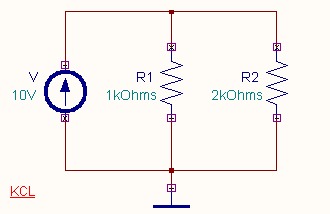
Kirchoff’s Current Law states that "in any electrical network
the algebraic sum of the currents meeting at a point is zero".
|

|

|
Kirchoff’s Voltage Law
|
|
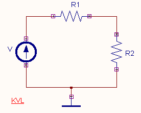
Kirchoff’s Voltage Law states that, "In any electrical network the algebraic
sum of the product of currents and resistances in each of the conductors in any closed
path plus the algebraic sum of the emfs in that path is zero. |

|

|
Procedure:- |
The circuit diagram is drawn by
loading components from the library to Schematic Editor page in EDWinXP Project Explorer. Wiring and proper net assignment has been made. The
values are assigned for relevant components. Kirchoff’s current law and
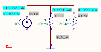
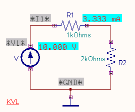
Kirchoff’s voltage law circuit diagrams in Mixed mode simulator are shown below. |
|
|
Mixed Mode Simulator is enabled from Preferences menu. The circuit is preprocessed.
The desired test points and waveform markers are placed. The Transient Analysis parameters
have been set. The Transient Analysis is executed. The test points display the values of
the current through the resistors. Hence we can prove the Kirchoff’s Laws. |
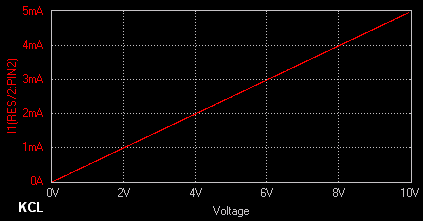
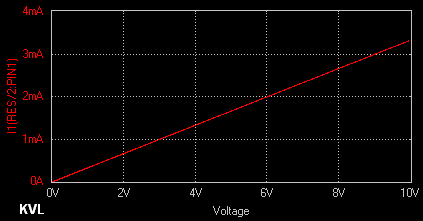
The variation of current through the two resistors with respect to
variation in voltage is obtained by performing DC Sweep Analysis. To perform DC Sweep
Analysis, a current waveform marker is placed at the resistor node. The sweep parameter
(voltage) for input source is set in the Analysis window. The applied voltage is swept
from an initial value of 0 to final value of 10V in steps of 10mV. The DC Sweep Analysis
is executed and the corresponding waveforms are observed in the Waveform Viewer.
|
Result:-
|
The output waveform may be observed in the waveform viewer The DC Sweep
Analysis results are shown below. |
|
|