Differentiator
Aim
To design and simulate a Differentiator circuit.
Components
|
Name
|
EDWin Components Used |
Description |
Number of components
required |
| RES |
RC05 |
Resistor |
1 |
| CAP |
CASE-A600 |
Capacitor |
1 |
| VGEN |
VGEN |
Ac voltage source |
1 |
| GND |
SPL0 |
Ground |
1 |

Theory
A circuit in which output voltage is directly proportional to the derivative of
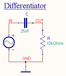
input is known as a differentiating circuit. A differentiating circuit is a simple RC series circuit with output taken across the resistor R.
In order to achieve good differentiation, the following conditions
should be satisfied:
- The time constant RC of the circuit should be
smaller than the time period of the input wave.
- The value of Xc should be 10 or more times larger than R at operating frequency.
Let ei be the input alternating
voltage and i be the resulting alternating current. The
charge q on the capacitor at any instant is
 ec
ec
 C
ec
C
ec
 ec
ec
Since capacitive reactance is
very much larger than R, the input voltage can be considered to be equal
to the capacitor voltage with negligible
error. i.e.
ec = ei
 ei
ei
Output Voltage, eo = iR
 ei
ei 
 ei
ei
 (input)
Hence the output is proportional to the time derivative of the input.
Procedure
EDWinXP-> Schematic Editor: The circuit diagram is drawn by loading components from the
library. Wiring and proper net assignment has been made.

The values are assigned for relevant components.
EDWinXP-> Mixed Mode Simulator:
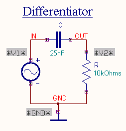
The circuit is preprocessed. The test points and waveform markers are
placed in input and output of the circuit. GND net is set as reference net. The Transient
Analysis parameters have been set. The Transient Analysis is executed and
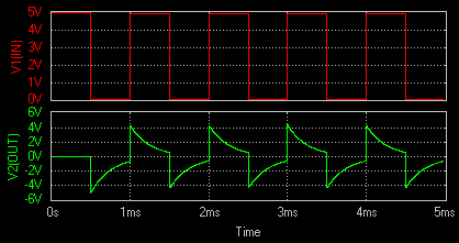
output waveform is observed in Waveform Viewer.
Result
The output waveform may be observed in the waveform viewer.
