WEIN BRIDGE OSCILLATOR USING 741
Aim
To simulate a Wein Bridge Oscillator circuit.
Components Required
Opamp – 741 (1), Resistor – RC05 (4), Capacitor-CC0805(2),DC Voltage source – VDC (2), Ground – SPL0 (3)
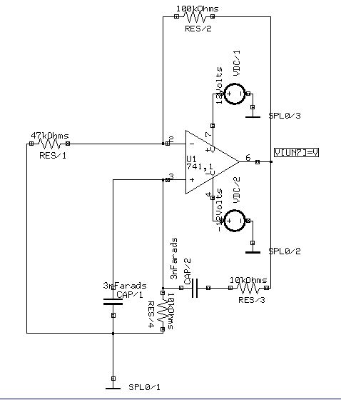
Circuit Diagram
Procedure
Draw the circuit diagram after loading components from library. Assign net names for connections wherever necessary. Preprocess the circuit by invoking Simulation → Preprocess. Place waveform markers on the output nodes. For placing waveform markers, select Tools → Instruments → set wave form Contents → Voltage waveform → Click on the required net and place the waveform marker. Run transient analysis after setting up required parameters.
To proceed with the simulation, the steps are as follows
Select Tools → Components → Component properties→ Change simulation parameters→ Click on the required component and change its values.
The values to be provided to the components are
OPAMP: 741(1) (Since it is subcircuit, no need of parameters to be set)
Resistors : RES/1 = 47k, RES/2 = 100k , RES/3=RES/4=10k
Capacitor : CAP/1 = 3nF, CAP/2 = 3nF
VDC/1 : 12V
VDC/2 :-12V
For setting up simulation time and analysis types, select Simulation menu, choose Analysis. In the window pops up, select DC Transfer function analysis from tree view.
Enter following values:
Step : 100µ
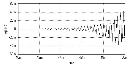
Final time : 50m
Start Time : 40m
Results : Select Waveform from drop down menu.
Click on Accept. Expand the Transient Analysis and select Waveform viewer, Select As Marked. Click on Accept. Select Transient Analysis. Run Analysis by clicking on Run button.
Result