Analyze the thermal effects on the board
Right click on the task PCB LAYOUT in the Project Explorer to unfold a list of functions. Clicking on Thermal Analyzer in this list opens up this module.
To understand the thermal analysis, example project SPICDEMO.EPB is used.
From the drop down list of the File menu of Project Explorer, select Open Project and select a project. Load the project SPICDEMO.EPB from \Job directory.
The components are arranged such that the thermal contours are symmetrical. This is decisive in the performance of a symmetrical design (as this one).
The steps followed for analyzing the board are as follows:
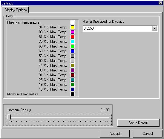
1. Right click on the workspace and select the tool
Display Parameters. Or select 5”) and set the Isotherm density to (0.1°C) for better analysis result.
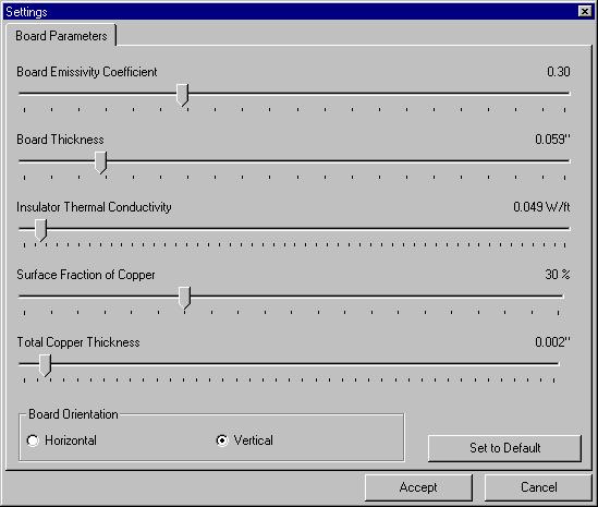
2. Right click and select the tool  Board Parameters (Or select from the Analysis menu). The board
parameters are set to the default values by clicking the SET TO DEFAULT button
as shown below.
Board Parameters (Or select from the Analysis menu). The board
parameters are set to the default values by clicking the SET TO DEFAULT button
as shown below.
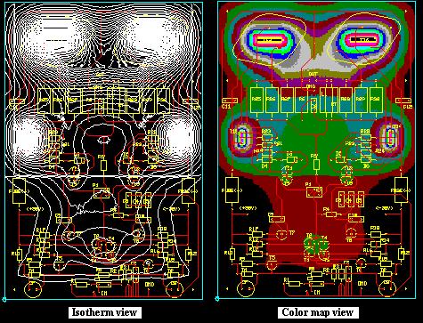
3. After supplying necessary parameters, right click and select the tool  Execute to execute the analysis. The result is displayed in the form of
isotherms and color mapping of the board may be viewed by switching on the
option
View/ Analysis Results/ Colored board.
Execute to execute the analysis. The result is displayed in the form of
isotherms and color mapping of the board may be viewed by switching on the
option
View/ Analysis Results/ Colored board.
4. The analysis result is as shown below:
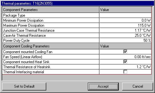
5. From the result it may be seen that the power transistors T15 and T16
get heated up to more than 200°C. So a heat sink of about 1.2°C/Watt may be of
use. Also, driver transistors T13 and T14 may require a heat sink of about
7°C/Watt. To simulate the heat sink effect, select the tool  Component Parameters and click on the component T15. A Thermal
Parameters
window pops up where you may set the cooling parameter for the component.
Enter the Thermal Resistance of Heatsink (e.g. 1.2°C/Watt) value and click OK.
Component Parameters and click on the component T15. A Thermal
Parameters
window pops up where you may set the cooling parameter for the component.
Enter the Thermal Resistance of Heatsink (e.g. 1.2°C/Watt) value and click OK.
6. Labels may be placed to display the temperature at various points on the board. For this right click and select the tool  Set/ Delete Label and click on the board at required locations. Label gets tagged to the cursor. Now drag the mouse to place the label at proper place.
Note: To delete the isotherm label click again on the label.