PIC Simulation
How to simulate PIC circuits
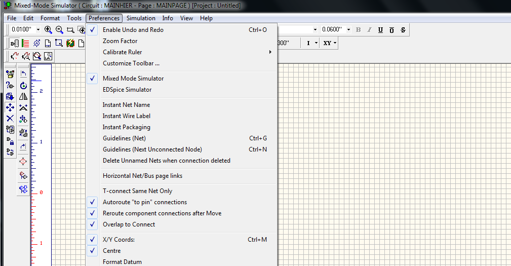
For a component to be simulated in Mixed Mode simulator, you should enable Mixed Mode Simulator in Preferences menu as follows.
Ensure that the component should have corresponding simulation function assigned to it, which will contain information about its behavioral characteristics, the simulator uses to construct the final output. The example given below will help you that how to simulate PIC micro controller. The system has a simulation function assigned for PIC micro controller.
Procedure
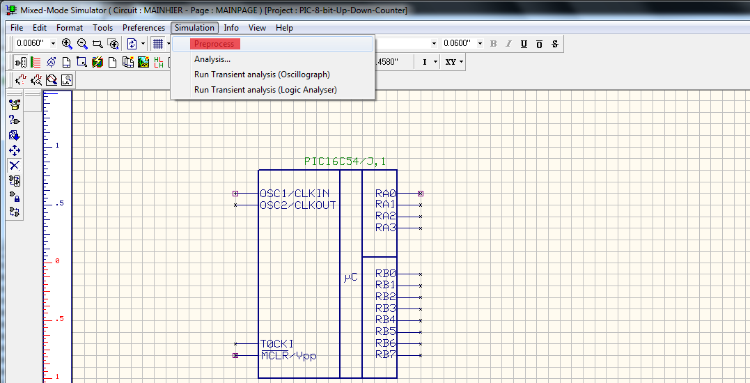
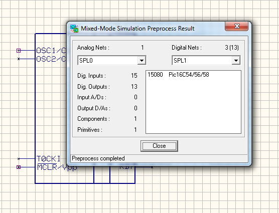
Draw the circuit diagram by loading components from the library. Wiring and proper net assignment has been made. Check if all the components are assigned with simulation parameters and the values are assigned for relevant components. The circuit is preprocessed as follows.
Select Simulation → click Preprocess → a pop up window will open ,click CLOSE. As shown in below pictures.
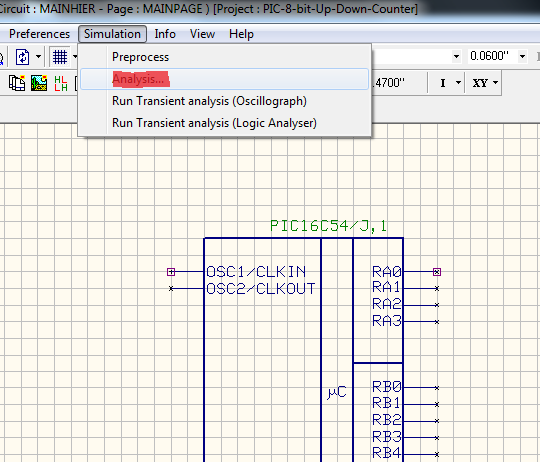
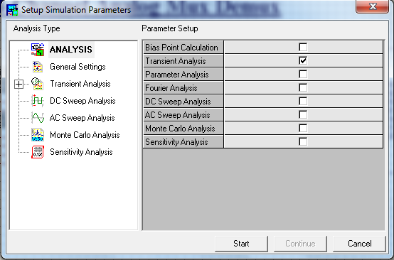
The output of the circuit is observed by running Transient Analysis. The Transient Analysis parameters can be set as,
Select Simulation → Analysis → Transient Analysis.
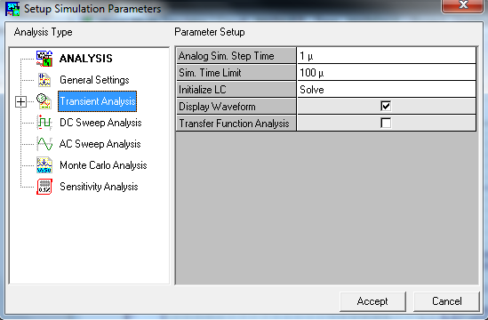
Analog Sim.Step time and Sim.Time Limit is to be set. Select Display waveform . Click Accept. Select Start to run the analysis. The Transient Analysis is executed and output observed in the Waveform Viewer
For Example:
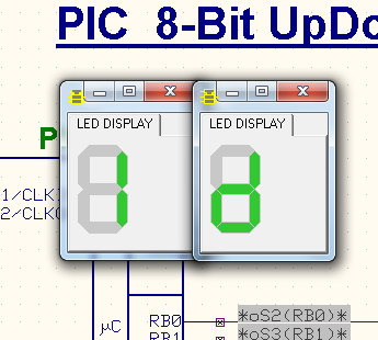
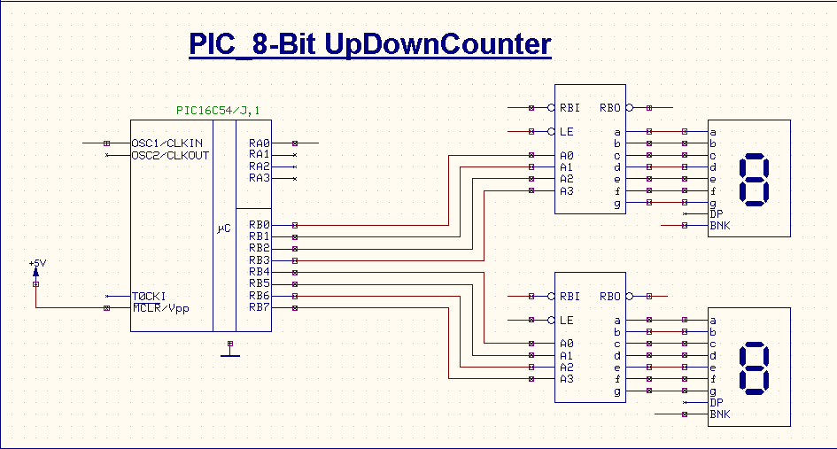
PIC 8-Bit UpDownCounter
Step 1:
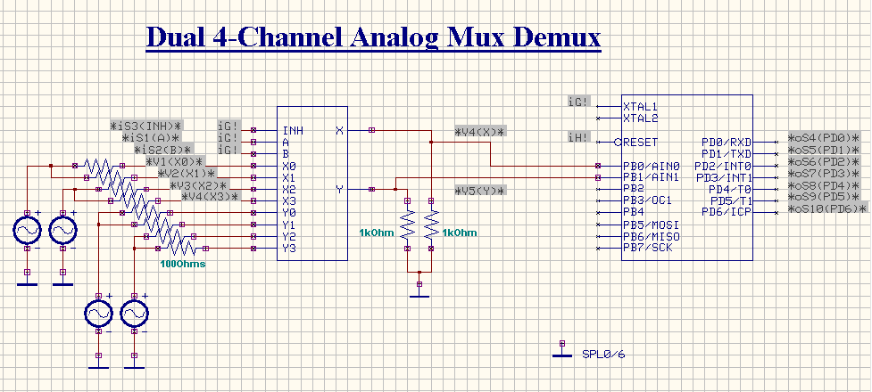
Load the components as in below diagram and connect them as in circuit. The components used in the circuits are PIC16C54,9368 , LEDDISP.
Step 2:
Set clock pulse to BNK pin of LEDDISP also OSC1 pin of PIC16C54 is provided with a clock pulse.
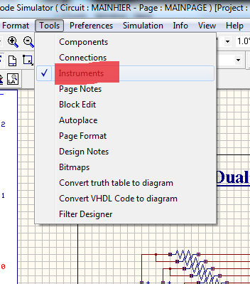
Select Instruments from Tools → Select preset logic state → Click clock generator
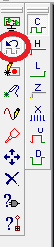
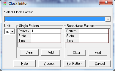
Click on pins where you want to set clock pulse, a pop up window will open shown in below picture , and set clock as you need.
Step 3:
Set preset HIGH logic state on required places as in the circuit.
Select Instruments from Tools → Select preset logic state → Click HIGH State. As we have did in previous step, select HIGH State. Place the HIGH state logic on required pins of the given components.
Step 4:
Set waveform marker at required places. To placing waveform markers,
Select Tools → Instruments → Set waveform Contents → Select the required type of waveform marker → Click on the required net and place the waveform marker.
Step 5:
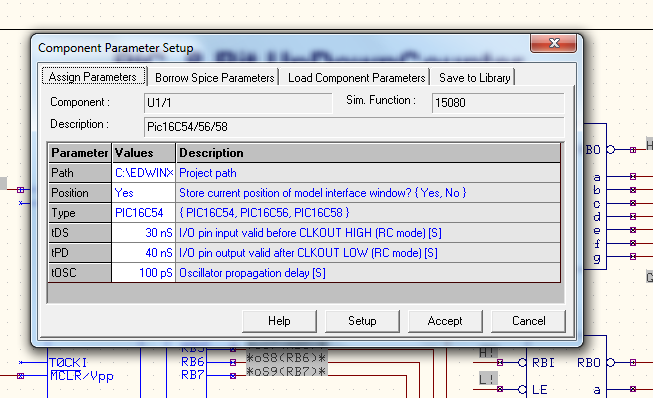
To perform the simulation of the micro controller, the steps included as follows. Select Mixed Mode Simulator → Tools → Instruments → Component Properties → Change simulation parameters → Click on PIC a window will appear as below.
Write code in the C Editor or the Assembly Editor, After writing the code , select Build to compile
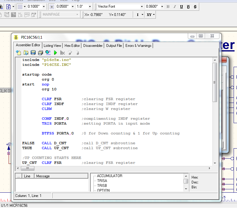
Program for PIC_8-Bit Up Down Counter is given below,
include "p16c5x.inc"
include "P16C5X.INC"
startup code
org 0
start nop
org 10
CLRF FSR ;clearing FSR register
CLRF INDF ;clearing INDF register
CLRW ;clearing W register
COMF INDF,0 ;complimenting INDF register
TRIS PORTA ;setting PORTA in input mode
BTFSS PORTA, ;0 for Down counting & 1 for Up counting
FALSE CALL D_CNT ;call D_CNT subroutine
TRUE CALL UP_CNT ;call UP_CNT subroutine
;UP COUNTING STARTS HERE
UP_CNT CLRF FSR ;clearing FSR register
CLRF INDF ;clearing INDF register
CLRW ;clearing W register
TRIS PORTB ;setting PORTB in output mode
MOVLW 0X00 ;moving literal constant 0x00 to W
MOVWF 08H ;moving the content of W to 08H
REP1
MOVWF PORTB ;moving the content of W through PORTB
INCF 08H,1 ;incrementing the content of 08H
MOVF 08H,0 ;moving the content of 08H to W
GOTO REP1 ;repeating the loop REP1
;UP COUNTING ENDS HERE
;DOWN COUNTING STARTS HERE
D_CNT CLRF FSR ;clearing FSR register
CLRF INDF ;clearing INDF register
CLRW ;clearing W register
TRIS PORTB ;setting PORTB in output mode
MOVLW 0XFF ;setting the start value
MOVWF 08H ;moving the content of W to 08H
REP2
MOVWF PORTB ;moving the content of W through PORTB
DECF 08H,1 ;decrementing the value of 08H
MOVF 08H,0 ;moving the content of 08H to W
GOTO REP2 ;repeating the loop REP2
;DOWN COUNTING ENDS HERE
RETLW start
END ; directive 'end of program
Step 6:
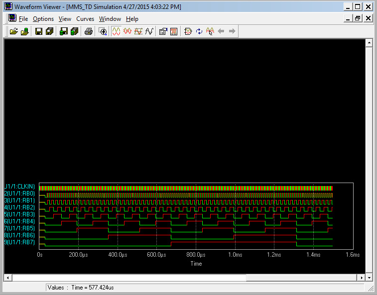
The Transient Analysis parameters have been set from Simulation → Analysis → Transient Analysis.
Output Window: