RC Phase Shift Oscillator
Aim
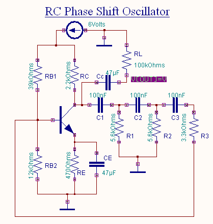
To simulate a RC Phase Shift Oscillator circuit.
Components
Name |
EDWin Components Used |
Description |
Number of components required |
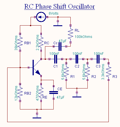
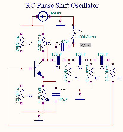
| TRANSISTOR | BC107A | Transistor | 1 |
| RES | RC05 | Resistor | 8 |
| CAPACITOR | CAP | Capacitor | 4 |
| VDC | VDC | Dc voltage source | 1 |
| GND | SPL0 | Ground | 3 |
Theory
An oscillator is a circuit, which generates ac output signal without giving any input ac signal. This circuit is usually applied for audio frequencies only. The basic requirement for an oscillator is positive feedback. The operation of the RC Phase Shift Oscillator can be explained as follows. The starting voltage is provided by noise, which is produced due to random motion of electrons in resistors used in the circuit.
The noise voltage contains almost all the sinusoidal frequencies. This low amplitude noise voltage gets amplified and appears at the output terminals. The amplified noise drives the feedback network which is the phase shift network. Because of this the feedback voltage is maximum at a particular frequency, which in turn represents the frequency of oscillation. Furthermore, the phase shift required for positive feedback is correct at this frequency only. The voltage gain of the amplifier with positive feedback is given by
![]()
From the above equation we can see that if ![]() . The
gain becomes infinity means that there is output without any input.i.e. the amplifier becomes an oscillator. This
condition >
. The
gain becomes infinity means that there is output without any input.i.e. the amplifier becomes an oscillator. This
condition >![]() is known as the Barkhausen
criterion of oscillation. Thus the
output contains only a single sinusoidal frequency.
In the beginning, as the oscillator is switched on, the loop gain Ab
is greater than unity. The oscillations build
up. Once a suitable level is reached the gain of the amplifier decreases,
and the value of the loop gain decreases to unity. So the
constant level oscillations are maintained. Satisfying the above conditions of oscillation
the value of R and C for the phase shift network is selected such that each RC
combination produces a phase shift of 60°. Thus the total phase shift produced by the
three RC networks is 180°. Therefore at the specific frequency fo the total
phase shift from the base of the transistor around the circuit and back to
the base is 360° thereby satisfying Barkhausen criterion. We select R1=R2=R3* =R and C1=C2=C3=C
is known as the Barkhausen
criterion of oscillation. Thus the
output contains only a single sinusoidal frequency.
In the beginning, as the oscillator is switched on, the loop gain Ab
is greater than unity. The oscillations build
up. Once a suitable level is reached the gain of the amplifier decreases,
and the value of the loop gain decreases to unity. So the
constant level oscillations are maintained. Satisfying the above conditions of oscillation
the value of R and C for the phase shift network is selected such that each RC
combination produces a phase shift of 60°. Thus the total phase shift produced by the
three RC networks is 180°. Therefore at the specific frequency fo the total
phase shift from the base of the transistor around the circuit and back to
the base is 360° thereby satisfying Barkhausen criterion. We select R1=R2=R3* =R and C1=C2=C3=C
The frequency of oscillation of RC Phase Shift Oscillator is given by
![]()
At this frequency, the feedback factor of the network is ![]() . In order that
. In order that ![]() it is required that the amplifier gain
it is required that the amplifier gain ![]() for oscillator operation.
for oscillator operation.
Procedure
EDWinXP -> Schematic Editor: The circuit diagram is drawn by loading components from the library. Wiring and proper net assignment has been made. The values are assigned for relevant components.
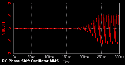
EDWinXP -> Mixed Mode Simulator: The circuit is preprocessed. The waveform marker is placed at the output of the circuit. GND net is set as reference net. The Transient Analysis parameters have been set. The Transient Analysis is executed and output waveform is observed in Waveform Viewer.
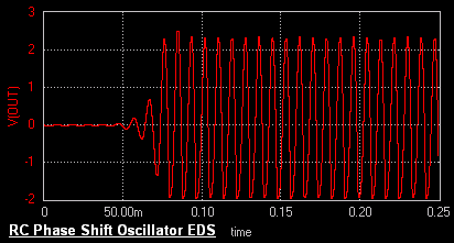
EDWinXP-> EDSpice Simulator: The circuit is preprocessed. The waveform marker is placed at the output of the circuit. The Transient Analysis parameters are also set. The Transient Analysis is executed and output waveform is observed in Waveform Viewer.
Result
The output waveform may be observed in the waveform viewer.