The ODB++ import allows importing projects of CAD packages which supports ODB++ formats to EDWinXP. ODB++ import is intended for the importing of data for the Layout with pure graphics information and/or with the netlist information. It is important to note that during the ODB++ import, no schematic diagrams will be created or reconstructed.
Import of each ODB++ job step consists of three automatically following phases. Three phases are as follows.
- The program reads EDA part (packages, components and netlist).
- Geometrical features (positive polarity only) of board layers are imported.
- The reconstruction of read data into editable EDWinXP database objects (This stage is optional.
The geometrical elements (traces, footprints, and copper areas) in phase 2 is stored as packages in project library, separately for each layer. These packages are placed on the board as components. Since packages can be edited in Library Editor, it is possible to modify PCB design in this way and generate manufacturing outputs. After importing the file, the components and different layers will be created as packages. They can be viewed from Library Explorer -> Packages -> Project Library. 1_SMD refers to the SMD component, 1_THD refers to the PMD component and MAINHIER_xx refers to the layer patterns which are imported during the ODB++ import. It will consists of drill files, information about different layers,
During reconstruction phase (if the Skip Recontruction is not checked), graphic elements stored in packages are converted into traces, via holes pad stacks and pad stacks for component footprints. The program relies on EDA information imported in phase 1 and their links to individual features. Each successfully converted item is removed from the package. Some of the imported features may be left over in packages after reconstruction because there was no clear information linking them to individual objects (like nets, components or packages). These may still be edited, output or used as templates.
Procedure
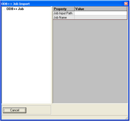
1. Invoke ODB++ Import from Project -> Import ODB++ Job
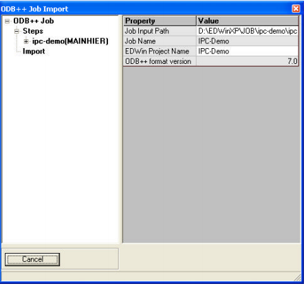
2. Browse and select the Job Input path
3. After choosing the Job file, then select ‘Import’ and click the Import button
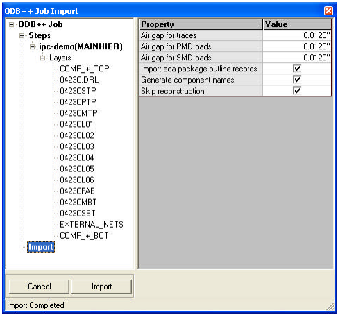
4. After importing the components and layer patterns will the generated in the package project library and the PCB will be generated in the Layout Editor.