LED
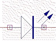
Schematic Symbol : LED,GLED,OrLED
Simcode : 5000,-5012,-5013
The LED will light when it conducts. By changing the simulation code of the component, we can have 3 different color LEDs Red,Green and Yellow(Amber).
How to simulate:
From Schematic Editor window, invoke Mixed Mode Simulator from Preference menu.
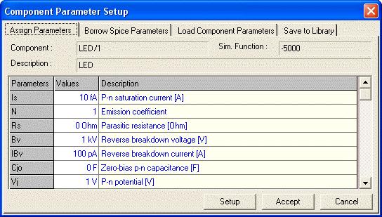
The simulation parameters can be changed by selecting Tools menu --> Instruments -->Component Properties --> Change Simulation Parameter and then clicking on the model. The Component Parameter Setup window will show the default parameters set for the component. If needed the parameters can be changed.
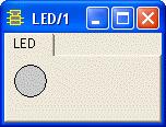
Click on the Setup Button. This will open the LED MMI window. Place this window accordingly so that it will display on the set position while simulation is running.
To simulate the model select Simulation menu -->Analysis -->Transient analysis OR Oscillograph or Logic Analyzer.