Digital Switch
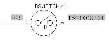
Schematic Symbol :DSWITCH
Simcode : 12005
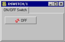
This is the model of a toggle switch. The initial state (ON/OFF) can be set before running simulation. During simulation, the user can toggle the state.
This instrument model is grouped under ‘Instruments’ category in the Schematic Browser.
How to simulate:
Invoke Mixed Mode simulator from EDWinXP Schematic Editor -> Preferences menu. Physical connections if any are made to the digital switch symbol and logic waveform marker is placed to view the waveform.
The input clock signal is given by selecting Instruments -> Preset Logic State -> Clock Generator.

The simulation parameters are then assigned by selecting Tools menu-> Instruments-> Component Properties->Change Simulation Parameter and then clicking on the model.

The initial The initial state is specified in the above dialog.
On clicking Setup, a window pops up. This window can be resized as required. To simulate the model, select Simulation menu -> Analysis -> Transient analysis OR Oscillograph OR Logic Analyzer
Each time the ON/OFF button is clicked, the output varies accordingly