Netlist / Wirelist Export Import
The procedure to import EDWinXP Schematic Netlist is as described below
Before importing the files, copy and paste the *.wrs and *.wrl files in the JOB directory also the component names in the wrs file should contain the name of the part in the EDWinXP library.
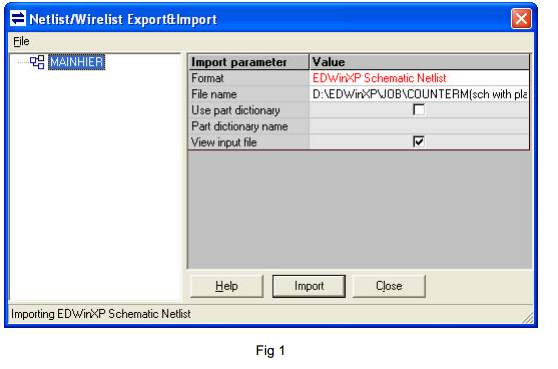
- Select Project → Netlist/ Wirelist Export & Import
- Choose File → Import
- Select EDWinXP Schematic netlist for the “Import parameter” → Format
- Browse and select the required project file whose schematic is to be generated. It’s optional to choose the ‘Part Dictionary name’. Click on Import
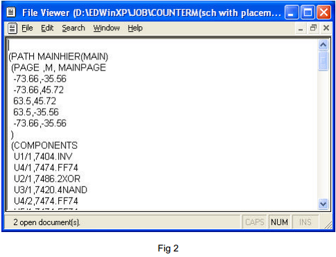
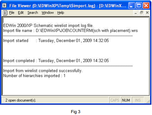
- After importing the wrs file, the wrs file as well as the import log file will be generated. These are given in the below two images (Fig 2 and fig 3)
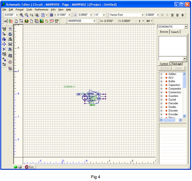
- After the import is completed, invoke the Schematic Editor. You can view the components are generated and will be stacked at the middle of the page. This is as given below (fig 4)
- Inorder to place the components in the Schematic Editor , you can autoplace the components using the Autoplace option. This function can be accessed from Tools → Autoplace. Before autoplacing, the Placement parameters and Design rules has to be set first which can be accessed from Autoplace parameters → Display parameters
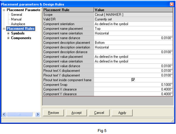
- For that invoke display parameters and select ‘Placement Rules’and set the parameters as given in the image below (fig 5)
- After giving all the necessary input to the Value, click on Apply button so that all the parameters get applied.
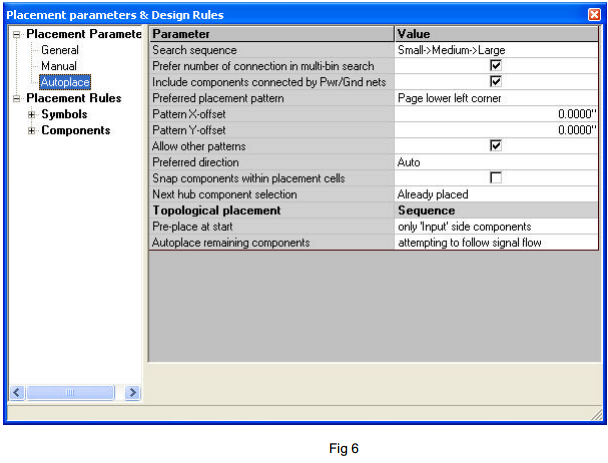
- Then select ‘Placement Parameters’ → Autoplace and then set the values as given in the below image (fig 6). We are following the Topological placement of components. Hence set the Sequence as given
- Pre-place at start - only ‘input’ side components
- Autoplace remaining components - attempting to follow signal flow
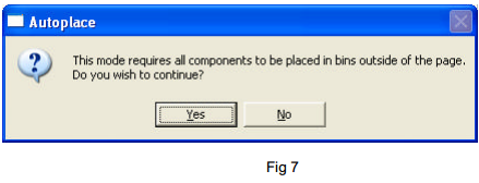
- Then select Autoplace all components (fifth function tool) → Autoplace topologically Fig 7
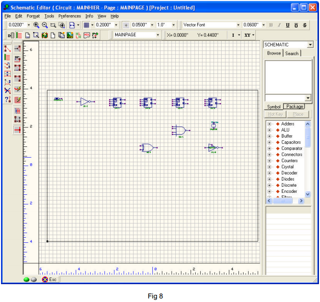
- Click on Yes to proceed with the autoplacing. The autoplaced components will be distributed in the schematic as shown below (fig 8).
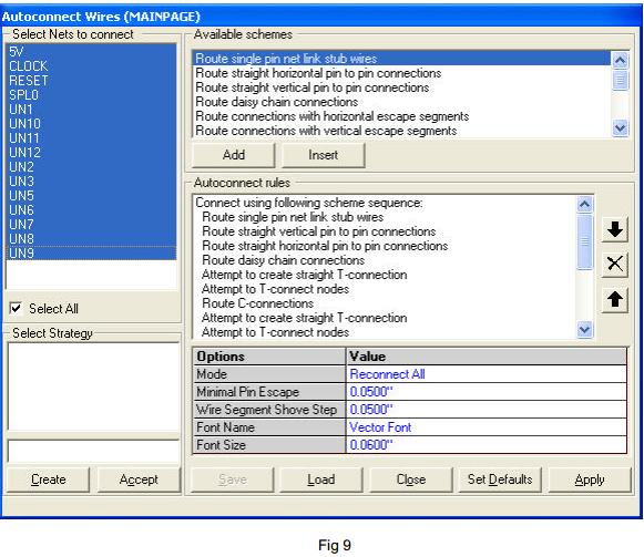
- For autorouting of the components, select Tools → Connections → Connect Components (first function tool) → Autoconnect all wires (F6) (sixth option tool) (fig 9).
- Choose Select All check box to select all the nets. Then click Apply → Close (Fig 9).
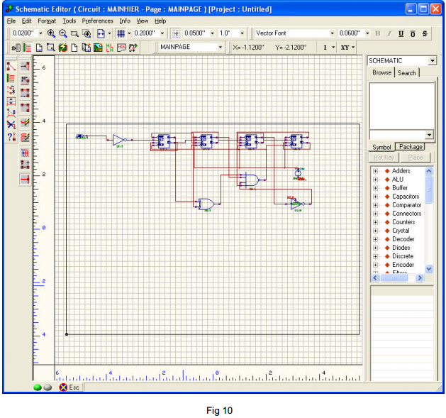
- The circuit will be autorouted as in the given image below (fig 10).