Create Hierarchical Block Diagram for Circuits
- Open EDWinXP from Start →Programs → EDWinXP - Main
- Click on Convert truth table to diagram

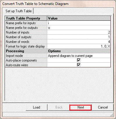
- In the window that appears, provide the number of inputs and outputs,choose format for logic state display and click next
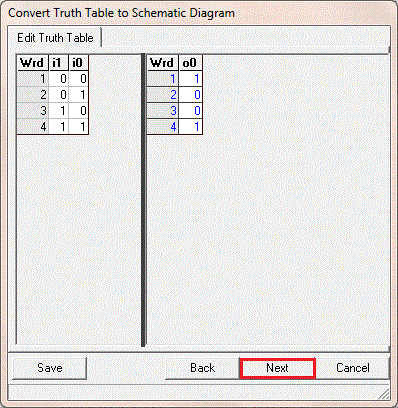
- In the window that appears, edit truth table and click next
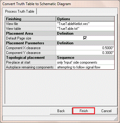
- In the window that appears,click finish
- place the circuit and save it by clicking on Save Circuit

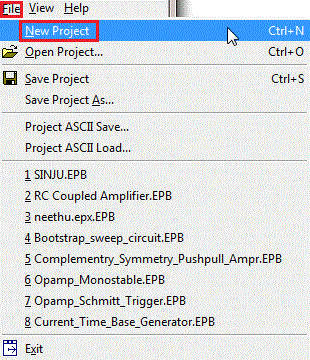
- Open a new project by clicking on File → New Project
- In the window that appears,click on Components
 → Add Components to the Circuit
 → Add block diagram element
- In the window that appearsprovide the ,number of inputs and outputs,click on next
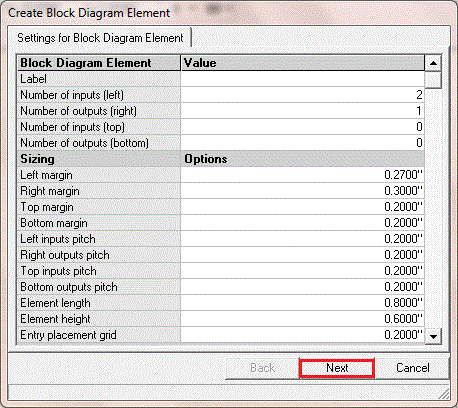
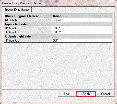
- In the window that appears,specify the entry names,click on finish
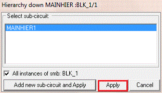
- Click on Hierarchy down
 and click on the circuit
- In the window that appears,select sub-circuit and click on apply
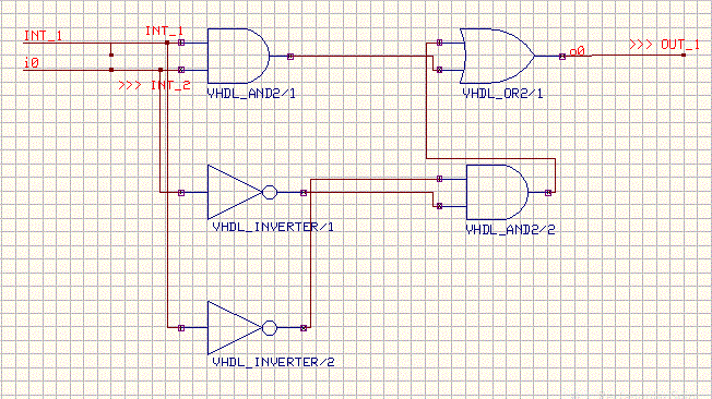
- Click on Relocate segment
 from Connections
  and choose Allow T-connections
- Place the components properly
Copyright © EDWinXP. EDWinXP is a trade name of DCT-China. All Rights Reserved.
→ Add Components to the Circuit
→ Add block diagram element
and click on the circuit
from Connections
and choose Allow T-connections
