Designer Capabilities
-
Chebyshev (Active Lowpass, Active Higehpass,
Active Bandpass, Active Bandstop)
-
Butterworth (Active Lowpass, Active Higehpass,
Active Bandpass, Active Bandstop)
-
Bessel (Active
Lowpass, Active Higehpass, Active Bandpass, Active Bandstop)
-
Elliptic(Cauer) (Active Lowpass, Active
Higehpass, Active Bandpass, Active Bandstop)
-
Ideal (Active
Lowpass, Active Higehpass, Active Bandpass, Active Bandstop)
Design Steps
Step 1: Evoke filter designer from Tools menu of
Schematic Editor.
Step 2: Select the required filter and set
the parameters .
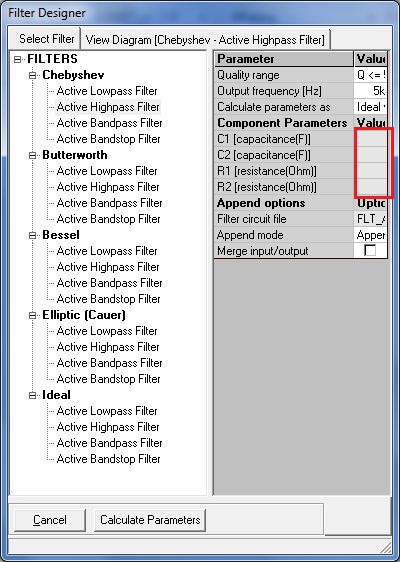
Step 3: After setting the parameters
click on Calculate Parameters Button. Component parameters values
are automatically calculated depending up on the output frequency.
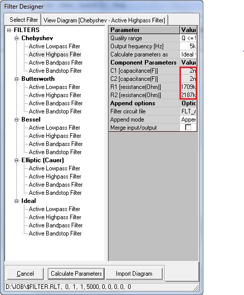
Step 4: Click on Import Diagram button. The Diagram of the filter will
get tagged to the cursor, place the diagram in the required position on the work
sheet.
To check the functionality
Step 1: From Tools| Instruments| Set Reference
Points, Keep AC IN + and AC IN - on input and ground node. Similarly AC OUT +
and AC OUT – on out put and ground mode.
Step 2: Keep wave form markers on input and
output nodes from Tools| Instruments| Set Wave form Contents |Voltage waveform.
Step 3: Enable either Mixed Mode Simulation or
EDSpice Simulation from preference.
Step 4: Preprocess the Circuit.
Step 5: Set the parameters for the AC Sweep
analysis.
Step 6: Execute the Analysis and observe the waveform.