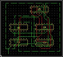
Creating Copper Pour Area
Copper pour areas are defined on the board to assign it as power/ ground plane. Copper pour areas of desired shape might be created to facilitate this purpose.
A Copper Pour Area may be created either in Layout Editor or in Fabrication Manager. Select
 Copper from the toolbar and right click on the workspace to popup a set of editing tools.
Click on Create graphics tool and enable the tool  Create Copper Pour Area.
Select COMP LAYER from Layer/ COMP SIDE/ COMP LAYER for the copper pour. Also select the net SPL0 from the Net combo box in Sizes Toolbar.
Now click on the workspace. A circle shows the start of copper pour area. Drag the cursor and click at positions where a vertex for copper pour area is to be defined. Proceed till the desired shape is obtained. Press END key or F6 to terminate the operation.
Now select NET 5V from the Select Net drop down in the toolbar. Repeat the process to create another copper pour area.