Parameter Sweep Analysis
This analysis mode allows to study the effect of variation of component parameters on the circuit. This is helpful in setting up the best operating conditions for the design, before detailed functional analysis is made.
1. Right click and select the function tool  Waveform Marker and then the
  Voltage Waveform option tool and define new Voltage testpoints on the nets, on generator input (between generator G and resistance RG), on transistor Collector and on amplifier load (between C2 and RL).
2. Click Analysis in the main menu. A window Setup Simulation Parameters opens with the option Analysis being highlighted on the left side of the window by default. Set the parameters by selecting GENERAL SETTINGS from the tree view on the left side of the window. Now, select the Parameter Sweep Analysis option.
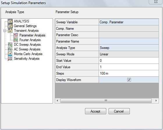
3. Select the Sweep Variable as ‘Comp. Parameter’. Move the cursor over Voltage Source and click the left mouse button. The selected component name and parameter name appears in the dialog box. Selected it has only one parameter, it is automatically selected. If we have more parameters, we will have to specify the parameter of the component, e.g., a transistor, from the drop down ‘Parameter Value’.
4. Set the values for the following parameter as shown below.
Start Value 1V
End Value 9V
Step 4V
5. Click ACCEPT button to automatically switch to Analysis option. Check Parameter Sweep Analysis check box. Now click START button for analysis to take place. The results may be viewed in the Waveform Viewer and the most suitable parameter value may be obtained.