AVR Simulation
How to simulate AVR circuits
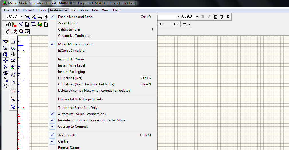
For a component to be simulated in Mixed Mode simulator, you should enable Mixed Mode Simulator in Preferences menu as follows
Ensure that the component should have corresponding simulation function assigned to it, which will contain information about its behavioral characteristics, the simulator uses to construct the final output. The system has a simulation function assigned for AVR micro controller.
Procedure
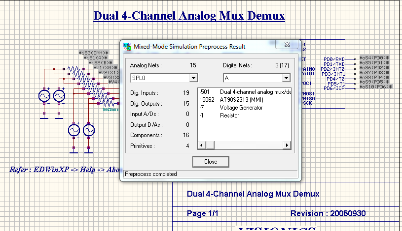
Draw the circuit diagram by loading components from the library. Wiring and proper net assignment has been made. Check if all the components are assigned with simulation parameters and the values are assigned for relevant components. The circuit is preprocessed as follows.
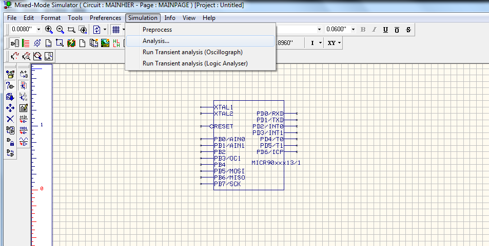
Select Simulation → click Preprocess → a pop up window will open ,click CLOSE. As shown in below picture.
The waveform markers are placed. For placing waveform markers,
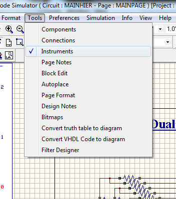
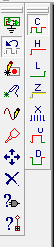
select Tools → Instruments → Set waveform Contents → Select the required type of waveform marker → Click on the required net and place the waveform marker
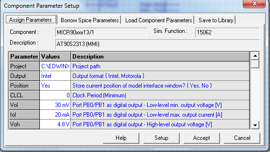
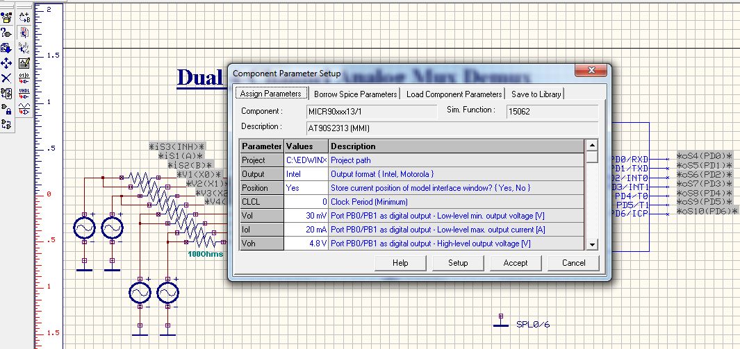
To perform the simulation of the micro controller, the steps included are as follows. Select Mixed Mode simulator → Tools → Instruments → Component properties → Change simulation parameters → Click on AVR , a window will appear as shown below
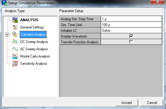
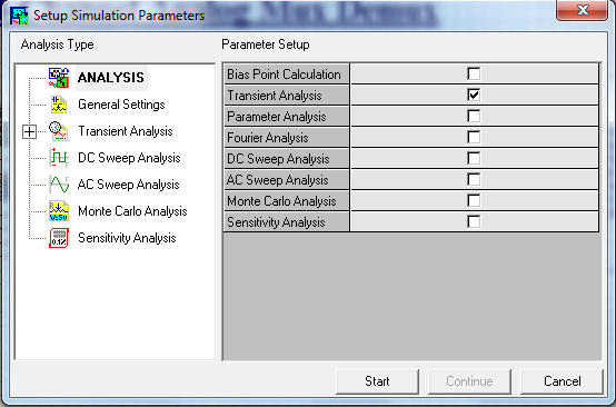
The Transient Analysis parameters have been set as,
Select Simulation → Analysis → Transient Analysis.
The Analog Sim.Step time and Sim.Time Limit is to be set. Select Display waveform . Click Accept. Select Start to run the analysis. The Transient Analysis is executed and output observed in the Waveform Viewer
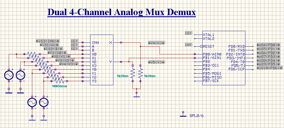
For Example: Dual 4-Channel Analog MUX and DEMUX
Step 1:
Load the components as in below diagram. The components used in the circuits are AT90S2313-10PC, MUL052, VGEN.
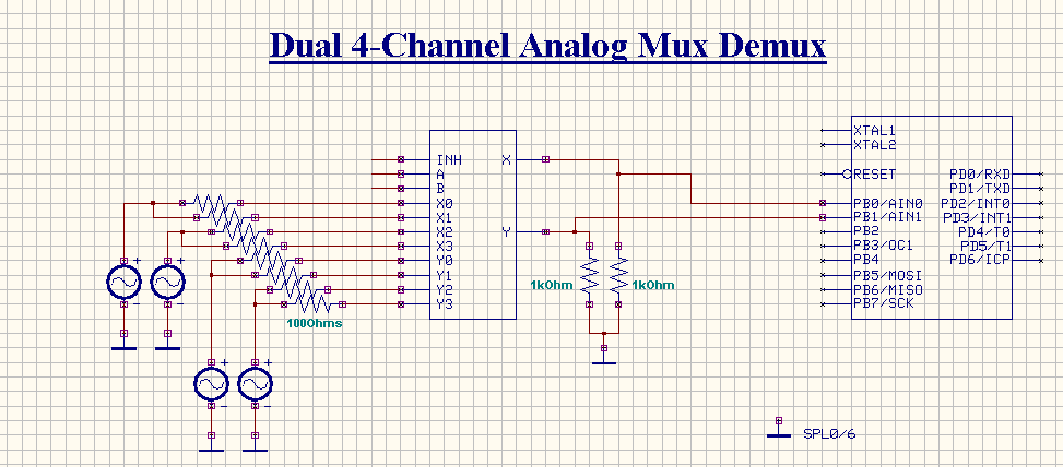
Set the resistors values as 100ohms for resistors at the input side of mux and as 1k for that at the output side. Also set source function as SINE ,PULSE,SINE and PULSE to VGEN/1,VGEN/2,VGEN/3 and VGEN/4 respectively
Step 2:
Set clock pulse to INH, A, B also XTAL1 pin of AT90S2313 is provided with a clock pulse
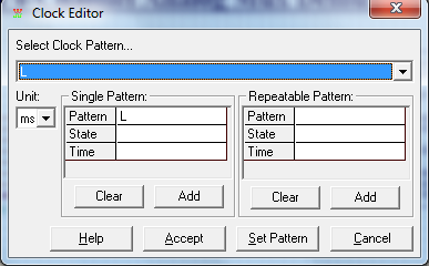
Select instruments from Tools → Select preset logic state → Click clock generator
Click on pins where you want to set clock pulse, a pop up window will open shown in below picture , and set clock as you need.
Step3:
Set waveform marker at required places. To placing waveform markers,
Select Tools → Instruments → Set waveform Contents → Select the required type of waveform marker → Click on the required net and place the waveform marker
Step4:
To perform the simulation of the micro controller, the steps included as follows. Select Mixed Mode Simulator → Tools → Instruments → Component Properties → Change simulation parameters → Click on AVR , a window will appear as below
Write code in the C Editor or the Assembly Editor, After writing the code , select Build to compile
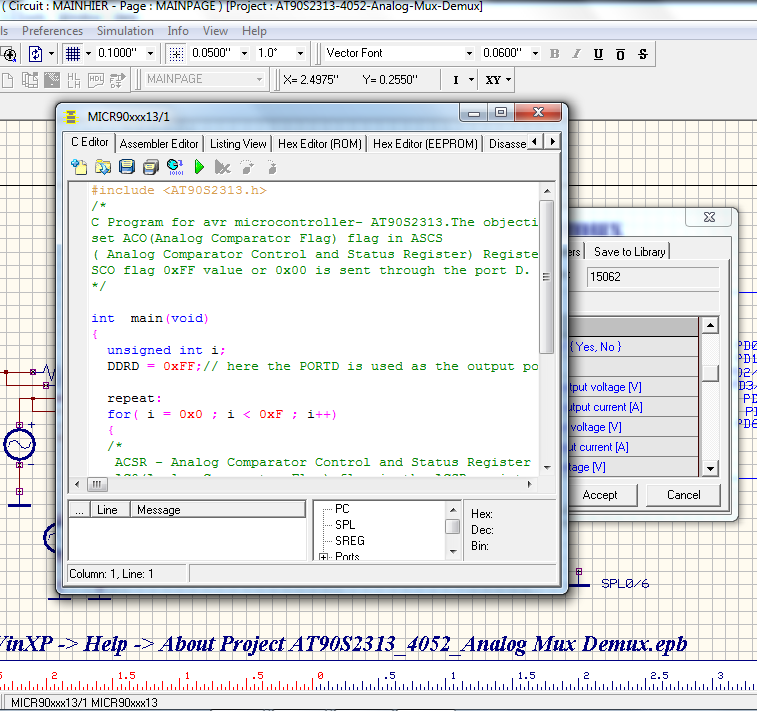
Program for Dual 4-Channel Analog MUX and DEMUX is given below
#include < AT90S2313.h >
/*
C Program for AVR micro controller AT90S2313.The objective of this program is to
set ACO(Analog Comparator Flag) flag in ASCS
( Analog Comparator Control and Status Register) Register. Based on the status
SCO flag 0xFF value or 0x00 is sent through the port D.
*/
int main(void)
{
unsigned int i;
DDRD = 0xFF;// here the PORTD is used as the output port.
repeat:
for( i = 0x0 ; i < 0xF ; i++)
{
/*
ACSR - Analog Comparator Control and Status Register
AC0(Analog Comparator Flag) flag in the ACSR register is set one
if ACO flag is set one then 0xff is sent to the output(PORTD).
If ACO flag is set to zero then zero is sent through output port (PORTD).
*/
if (bit_is_set(ACSR, ACO))
PORTD = 0xFF;
else
PORTD = 0x00;
}
goto repeat;
return 0;
}
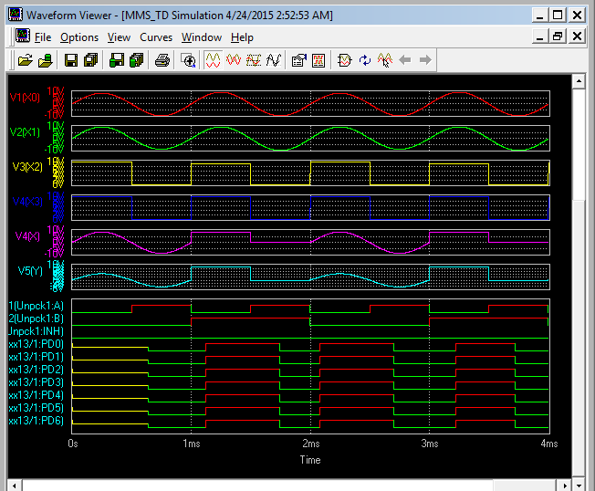
Step5:
The Transient Analysis parameters have been set from Simulation → Analysis → Transient Analysis.
Output Window